

Jim Krause | Classes | P356 TV Studio Production
Week 7
Agenda/reality check
- Graphics/Studio gear and signal flow quiz next week
- Cover switchers and other studio equipment
- News Update exercise in lab this week. Our anchors/reporters are:
- Monday: Aaron, Matt, Alivia & Ethan
- Wednesday: ?
- Produce Demonstration Videos next week and the week after. For this exercise (and all of the reminaing projects) you'll need to submit a 1-page (minimum) critique/review after it's been produced.
- Then the performance piece and then the PSAs.
PSA Reality Check - We will schedule PSAs in a few weeks. This week we'll finish pairing students.
Demonstration videos. The groups and schedule are posted here. We start producing these next week. Please keep in mind the requirements:
- Time: At least 3 minutes and no more than 6.
- Music/SFX: At least two cuts of music or sound effects (For example theme music at the beginning and end and demonstration music during show.)
- Graphics: At least three original graphics (the slate does not count :-)
We'll finish a few minutes early today to give you time to meet with your group members. Be sure to delegate responsibilties: audio design, graphics, set & lighting design, etc. We're shooting these starting next week.
Cybercollege Readings - 57 (timecode) & 60 (studio)
Signal Flow in the Studio
In a TV production studio you often hear the words "upstream" and "downstream." These terms use the analogy of water flow to represent the flow of the video signal to various pieces of equipment in the studio. Think of a camera as being the most upstream element in the studio. This is where the signal originates. After the signal comes out of the camera CCU, it flows downstream into the input of the switcher. Once inside the Grass Valley switcher in Studio 5, the signal flows from the Preview and Program busses to the keyer. So the keyer is downstream of the program bus. After the keyer, the video flows to the Master/Panic Black switch. So whatever we do on the Program or keyer stage can be covered by the Master/Panic Black button. After leaving the switcher, the video flows downstream to a VTR.
Studio Equipment
There are several important pieces of studio equipment that you should be familiar with: TBCs (time base correctors), waveform monitors, vectorscopes, and switchers.
TBC (time base corrector) - A piece of equipment used to correct instabilities in analog video signals, provide synchronization between video signals, and adjust phase differences in signals to correct color or make them consistent with other signals. TBCs usually have a "proc amp" which lets you "tweak" or adjust the video's brightness, hue, saturation and setup.
Waveform Monitor - A device used to examine the luminance portion of the video signal and its synchronizing pulses.
- ATSC/Digital black levels should be 0 IRE
- White level (both NTSC and digital) shouldn’t be any greater than 100 IRE on a waveform monitor
- 20 IRE units equals one f-stop
Vectorscope - A vector display measuring device that allows visual checking of the phase and amplitude of the color components of a video signal. NOTE: You can't adjust or manipulate a video signal just by using a waveform monitors and vectorscopes. They simply let you examine the signal. You must use a TBC, a camera control
Sync generator - Provides synchronizing pulses that are fed to the TBCs and cameras to keep them all running. All the horizontal/vertical retracing and scanning must happen at the same time in order to blend the video signals together with a switcher.
Switchers - Video switchers allow the user to select and mix video signals. They also provide a limited degree of effects.
Basic functions:
- Select appropriate source from several inputs
- Perform basic transitions
- Create/access special effects
Our Karrera switcher has 2 Mixed Effects Banks (ME1 and the Program Bus)
Switchers can have a number of different busses. A buss is simply a row of buttons, which allow the operator to select which input goes out to a particular destination. Usually there are at least three different busses on a production switcher:
- Program bus: whatever source is selected goes to the program monitor
- Preview bus: identical in appearance to the program bus
- Effects bus: used to select sources for different effects
Basic Operation:
- Cut or take (Ready 1- take 1)
- Flip flop of program/preview bus
- Dissolve: (standby 1- dissolve to 1)
- Super (superimposition: using the fade bar and keeping it halfway between sources)
- Fade: (a dissolve with black)
Special Effects & controls:
- Wipes & wipe patterns (see below)
- Key & clip controls (chroma key, luminance key)
- Downstream keyer
- Color background controls
Wipe: when one image replaces or uncovers another
Soft wipe: you can set the border to be soft (fuzzy) by a knob on the switcher
Wipe pattern: the geometric shapes you can choose from (diamond, circle,) these are standardized and referred to by numbers so that EDLs (edit decision lists) can pull them up consistently from various switchers
Wipe positions and directions: al wipes can be reversed (by pressing the reverse button on the switcher) or stopped partway by stopping the fader bar.
Split screen: if you stop a horizontal, vertical or diagonal wipe halfway you get a split screen.
DVE (digital video effect) allows you to actually squeeze, rotate, flip, shrink or expand the image. Grass Valley uses the abbreviation IDPM (Digital Picture Manipulation) instead of DVE- but they both mean the same. DVEs or DPMs allow for shaping or distoriting the video in interesting ways, including perspective, squuezes, page turns, flips etc.
Keys: When using keys, the switcher replaces part of the video signal with video from another source. There are several types of keys you can do with a production switcher: luminance keys, chroma keys and external keys.
- Luminance keys work on brightness. If someone is standing in front of a black background, you can use a luminance key, adjust the threshold, and key out the dark areas. Similarly you can key out the brightest areas of an image. The problem with this type of key is that it's not very precise. If we key out the dark areas, everything else that's equally dark will be removed as well (shoes, pupils in eyes, buttons, etc)
- Chroma keys work by selecting and removing specific colors. This is usually how the weatherman standing in front of a map is produced, or "on-location" shots of news people who areen't really on-location. The two most popular colors to use are blue and green. This is because these colors are usually farthest away from the color of people's hair and skin. Studios and production companies usually have both a green and a blue screen. If the talent shows up wearing blue, you use the green screen and vice-versa.
- External or Linear keys are fed by an external source, such as a character generator. The external device sends two video signals: the key and video fill. The key signal acts like a cookie cutter telling the switcher what video to remove. The video fill is what goes into the cut out portion.
Chromakey examples:
You should also be aware of the term downstream key, which is a key that happens downstream or after the video leaves the switcher. It's possible to get a downstream keyer that inserts the station ID or weather warnings, etc.
Karrera Keyer Features (video 4.5 minutes)
Switcher types & functions
The Grass Valley switcher in Studio 5 is just one type of switcher. There are several different types of switchers designed for different applications.
- Production switchers are used for live production. (like the Kayak Grass Valley we have in Studio 5)
- Post-production switchers (used for primarily for editing) Most of the switcher's functions (such as wipes, dissolves, etc.) can be remotely controlled by the Editing Control Unit. These are now rare as most editing is being carried out with non-linear systems (Avid, Final Cut Pro, etc.).
- Master control switcher: These are optimized for switching and controlling numerous video sources and playback devices (VCRs digital cart machines, etc.). These generally won't have a lot of effects but focus on video previewing and insertion of station IDs and weather warnings.
- Routing switchers: Similar in function to a patch bay. Some routing switchers are nothing more than a row of buttons. Some are computer-based and can be programmed with a variety of setups.
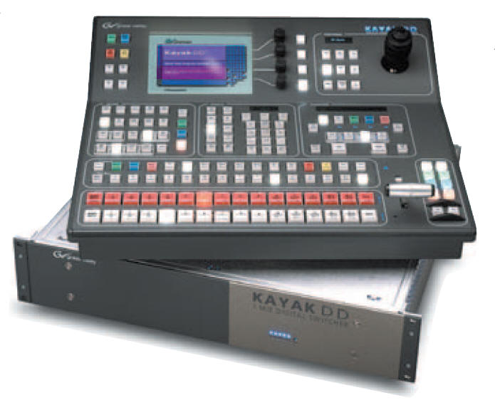
Production Switcher
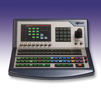
Master Control Switcher
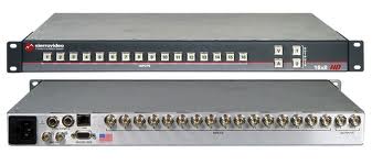
Simple Routing Switcher
Don't forget Audio
Audio follow video switchers - Audio switching is sometimes done by a separate device (other than the video switcher) The term "audio follows video" refers to devices that control or trigger an audio switcher. The result is that when you swicth a video source, the audio follows along.
Video Recording Systems
Tape - Open reel (obsolete) or cassettes (miniDV, DVCPro, HDCAM, etc.). Magentic tape has fallen out of favor due to advances in solid state and magentic storage drives, which offer greater longevity and non-linear / direct access.
Magnetic Disk - Uses one or more magnetic disk drives (commonly referred to as a "hard drive"). Mutlple drives are often cofigured as a RAID (redundant array of independent disks).
Optical Disk - Many camcorders write video directly to optical discs (Sony XD Cam, BluRay, etc.)
RAM-based (uses solid state memory) Now found in computers (SSD) and on consumer and professional camcorders. (Panasonic P2 cards, CF & SD cards, etc.)
Cables and Connectors
How does one get video from one device to another? Typically through a cable and a connector.
Digital video:
- USB (universal serial bus)
- SDI (Serial Digital Interface) Found on professional standard definition digital video devices. Can include embedded audio along with the video.
- HD-SDI - The high-definition version of the SDI digital interface.
- HDMI - High-Definition Multimedia Interface. Carries audio. (DVI-D, a computer display connector is partially compatible with HDMI but carries no audio.)
- TRIAX - Used to connect studio cameras to the CCUs
Digital audio:
- AES/EBU (AES3) Developed by the Audio Engineering Society and the European Broadcast Union. Typically uses 3 conductors with XLR connectors. Found on professional gear.
- S/PDIF (Sony / Philips Digital Interconnect Format) - Can be transmitted over coaxial (2 wires) or over optical (TOSLINK). Mainly found on consumer gear.
- TOSLINK (Toshiba Link) - Fiber optic.
