

Jim Krause | Classes | P356 TV Studio Production
Week 3
Announcements/Reality Check
- No lab / lecture due to MLK Day
- Next week:
- Camera Quiz (Quiz #1) in lecture.
- PSAs- Should find
a client by our next lab, as initial PSA Proposals are due in a few
weeks.
- Review PSA assignment
- Bring in a topic to discuss for our next lab and 5 questions to move discussion along. We will be producing a talk show, Studio 5 Perspectives".
- Don't forget about other major production assignments. Now is the time to be thinking about your demonstration video and dramatic scene.
Readings: Cybercollege units 15, 16, 17, 18, 19 & 20
Studio Gear
What are the cameras in the studio connected to?
CCU: camera control unit. Controls all aspects of the camera's operation. (except the lens)
Camera Shading - the engineer operating the CCU manually adjust the iris from shot to shot.
Sync generator: produces an electronic synchronization signal. This is used to time all the cameras together so their electronics are working in unison.
Vectorscope: A device that shows color information.
Waveform Monitor: A device for measuring brightness (luminance) levels and timing information. (Studio engineers use this when shading the cameras.) The scale is in IRE units. In this country (NTSC) digital black level is 0 IRE. The brightest portion of the video signal (ie. white clouds on a sunny day) should not exceed 100 IRE. So the darkest portion of a video signal will register at 0 IRE and the brightest possible white will be 100 IRE.
If you look at the display of a waveform monitor, you'll see registration lines, which are spaced at 20 IRE intervals. Each step up the grid on a waveform monitor (20 IRE) is equal to one f-stop.
Waveform monitors display brightness/luma information and can be built into camcorders and incorporated into field monitors. The major levels to be aware of are:
- 0 IRE - For the darkest (blackest black) portions of your video
- 100 IRE - For the brightest portion of the screen (E.g. white, fluffy clouds on a sunny day)
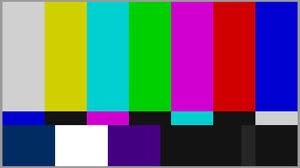
SMPTE color bars should look something like this:
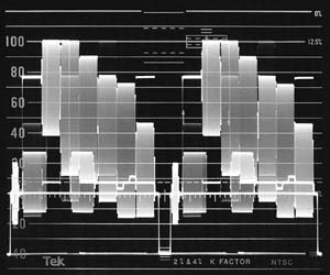
On a waveform monitor this is how they'd appear:
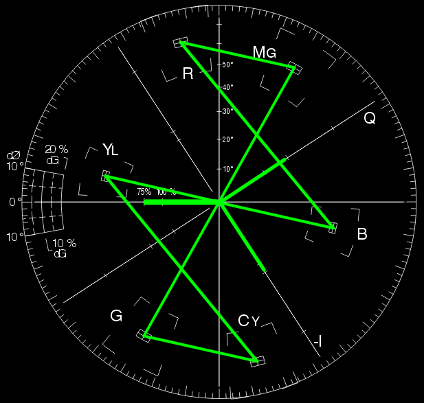
On a vectorscope display you'd see something like this:
Note the IRE values of the various colors. Remember that the maximum legal, allowable value for broadcast video is 100 IRE. The blackest black for digital video is 0 IRE.
The Video Signal --------------
Fields & Frames
Like film, the moving TV image we see is really a series of still frames. In a standard definition TV system these frames are taken and presented approximately 30 times a second. (The actual rate is 29.97 frames per second.) However each frame is actually made up of two interlaced fields. Field one displays all of the odd lines and field two displays all of the even lines. Together the two fields make up an interlaced frame of video.
It's important to understand that one field is the smallest sample of light (unless a different shutter rate is used) and that they are taken every 1/60th of a second. If you use a light meter with a camera shooting standard interlaced video, you'll set the frame rate on the light meter to 1/60th of a second. (Or 30 if the light meter offers a "cinema" mode.)
Progressive Scanning: The electron beam scans each line (not skipping even or odds etc)
Common formats supported by Digital TV include:
- 480i uses 480 scan lines at (approximately) 30 frames per second or 60 fields per second
- 480p uses 480 lines scanned at 60 frames per second
- 720p uses 720 lines at 60 frames per second (HDTV) 1280 x 720
- 1080i uses interlace scanning (HDTV) 1920 x 1080
